Ningbo Bohua Mechanical Parts Co., Ltd. · Linda, Export Sales · linda@ningbobohua.com · www.bohua-casting.com
Engineering guide
Aluminum Casting Porosity: Inspection and Acceptance
Porosity is a manufacturing and acceptance question tied to a particular casting. An indication in a radiograph, a pore exposed by machining and a failed leak test are different observations. Before comparing suppliers or deciding whether a part is acceptable, define the affected zone, part condition, inspection method and controlling requirement.
On this page
Investigate the Mechanism Before Choosing a Remedy
Gas-related porosity and shrinkage-related porosity can require different investigations. Review the alloy and melt records, filling route, venting, feeding, local section changes and solidification conditions. Do not identify the mechanism from a single surface photograph or assume that one process adjustment fixes every indication.
For gravity and low-pressure casting, the review may include melt handling, mold/core conditions, feeding and the pressure or pouring sequence. For high-pressure die casting, distinguish shot-sleeve behavior, cavity filling, venting or vacuum arrangements and intensification. The measurement location and machine stage matter when discussing a velocity or pressure setting.
| Possible mechanism | Where to investigate | Evidence to compare |
|---|---|---|
| Gas-related porosity | Melt condition, hydrogen, transfer turbulence, core or mold condition and venting | Melt-treatment and handling records, location of indications, and repeat inspection under the same method |
| Shrinkage-related porosity | Local heavy sections, bosses, rib junctions and flange-to-wall transitions | Feeding and solidification review, local section geometry, and selected sectioning or radiographic evidence |
| Machining exposure | Sealing lands, bores, threads and newly exposed pressure boundaries | Stock removal, as-cast versus machined inspection, and functional tests at the agreed stage |
At Bohua
Bohua has a vacuum hydrogen analyzer and an Oxford optical emission spectrometer. Its casting simulation software is AnyCasting. To scope an investigation with these tools, send us your drawing, porosity limits and required acceptance records.
For the manufacturing route, see Bohua's gravity casting equipment and scope. Keep the inspection plan tied to the selected route.
At Bohua
Bohua releases a heat for pouring after melt treatment only when both its vacuum hydrogen check and Oxford composition analysis are acceptable.
In the large-pump volute investigation, Bohua associated pinholes with inadequate hydrogen removal and inclusion indications with incomplete melt cleaning. Feeding was also investigated as a possible cause of other voids. A treatment check and a feeding review therefore addressed different questions.
Process Settings Need a Qualified Window
The supplier should establish a process window for the actual alloy, tooling, machine and geometry. Record which variable is controlled, where it is measured, its approved range, monitoring method and response to a deviation.
This guide does not supply a universal slow-shot velocity, switch point, mold-temperature tolerance or reduced-pressure-test threshold. If simulation is used, identify its assumptions and compare predictions with validation castings and inspection. A simulation result helps investigate a route; it does not provide a universal percentage accuracy or eliminate the need to validate the casting.
After a failure, record the affected lot, indication location, investigated cause, changed variable and reinspection result. Compare evidence from the same zones and delivery state before deciding whether the corrective action worked.
At Bohua
Bohua's confirmed rotary-treatment window for porosity control is 480–520 rpm over 15–20 minutes, with purge gas. For flux-assisted cleaning the baffle is raised; for degassing it is lowered to limit the vortex. The factory's reduced-pressure check accepts a slightly concave sample surface and a cut section that is essentially free of pores. A flash at the melt surface is an operator observation, not the acceptance test. Follow the rotary-degassing and reduced-pressure-test sequence for the factory account.
A reduced-pressure density index compares the densities of samples solidified at atmospheric and reduced pressure. It is not a direct hydrogen-concentration reading and does not locate pores in the finished casting. Report the test protocol before comparing results.
General method source: Tokatlı, Çolak and Yüksel, 2025 A356 melt-quality study. Its laboratory protocol is separate from Bohua's visual release check.
Match the Inspection Method to the Question
Choose each method for the evidence it can provide at the required location and production stage.
| Method | Useful question | Boundary to agree |
|---|---|---|
| Radiography | What internal indications are visible in the specified views? | Technique, image quality, thickness, coverage, reference images and interpretation criteria |
| Computed tomography | What geometry or indications can be evaluated in a defined volume? | Resolution, accessibility, segmentation, coverage and acceptance method |
| Sectioning or metallographic examination | What is present at the selected cut location? | Section location, preparation, measurement and whether the sample represents the required area |
| Functional leak or pressure test | Does the tested boundary meet the specified functional requirement? | Part condition, medium, conditions, stabilization, limit, sampling and records |
No method detects every possible defect in every part. A leak-test pass does not certify all internal material quality, and a radiographic result does not replace a specified functional test. Define the required evidence layers separately.
At Bohua
Bohua has Unicomp UNC-160 and Y.MU2000-D X-ray systems and a metallographic microscope. Air-under-water immersion is the leak-test method, with a pressure capability of 3 bar or more. The test pressure, hold conditions, test boundary, sampling and acceptance must be specified for the part.
Computed tomography is not on Bohua's confirmed equipment list. If a drawing asks for CT or destructive sectioning, name the provider before including either method in the order.
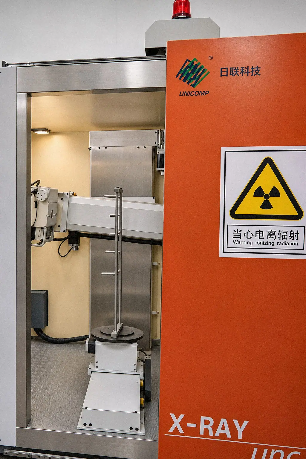

See Bohua's quality-control equipment for the factory scope. Define functional testing separately through the immersion leak-test specification guide.
At Bohua
The Bohua X-ray systems produce digital images evaluated using GB/T 11346-2018 and the customer's acceptance grade.
Identify the required grade and inspected zones in the order rather than applying an unrelated reference-image family automatically.
Use ASTM E505 Within Its Scope
The public scope of ASTM E505 covers reference radiographs for aluminum and magnesium die castings and describes three graded discontinuity categories with four severity levels. It should not be presented as a default acceptance standard for every aluminum casting process.
The purchaser and qualified inspection personnel should identify the applicable specification and edition, casting route, image type, thickness, inspection zones and agreed acceptance. A reference image classification does not automatically assign one acceptable level to all sealing faces or structural regions. For digital images, confirm the applicable reference and technique requirements rather than assuming a film-based reference can be transferred without review.
Source: ASTM E505-22, Sections 1.2 and 1.5. The edition discussed here is E505-22; its reference images are film-based.
Use the digital radiography RFQ guide for the technique, reference-family and interpretation fields.
Define Acceptance by Zone and Function
Create a zone map linked to the drawing. For each controlled area, identify the discontinuity type or functional risk, method, measurement definition, permitted condition, sampling and report.
Where a pore percentage or maximum indication size is required, state how it is measured and which approved requirement supplies the limit. This page provides no generic acceptable porosity percentage for automotive parts, sealing surfaces or pressure boundaries. A number without its zone, measurement method and acceptance source should not be used to release production.
Include bosses, thick mounting pads, rib junctions and flange-to-wall intersections when identifying potential feeding risks. For a coolant water outlet casting, map the flow boundary and machined sealing interface separately. The zone selection still depends on the actual drawing.
Control Machining Exposure and Repair
Machining can expose internal indications or alter the pressure boundary. Agree whether inspection or functional testing is required before machining, after machining, after finishing or at another approved stage. Connect the result to the tested part or batch.
If impregnation, weld repair or another recovery process is proposed, define permission, process approval, material compatibility, subsequent inspection and traceability. Do not promise a universal recovery yield. A repaired part must meet the agreed requirements and disclosure rules for that order.
At Bohua
Impregnation requires customer approval and is performed by a qualified subcontractor. If you are considering weld repair, request confirmation of the service scope and approval requirements before including it in the order.
Use the customer-approved impregnation policy to define permission and subsequent acceptance.
RFQ and Corrective-Action Evidence
Use the drawing and delivery state to define the evidence package:
- Drawing with critical zones, machining stock and final functional boundaries.
- Alloy, temper, casting route and delivered condition.
- Proposed inspection methods, coverage and standard editions.
- Acceptance criteria, sampling, records and interpretation responsibility.
- Repair restrictions and the approval path for deviations.
- Batch traceability and the investigation records required after a failure.
Ask the supplier how first samples validate feeding, when melt quality is checked, and what happens if machining exposes subsurface voids. Require the answer to identify the record, responsible person and reaction plan.
FAQ
Is zero visible porosity a universal requirement?
No. Use the specified method, coverage and acceptance criteria.
Does CT replace radiography and leak testing?
Not automatically. Select methods that answer the required material, geometry and functional questions and confirm their limits for the actual part.
What should accompany a porosity-related RFQ?
Send the drawing, affected zones, delivered condition, relevant inspection examples and required acceptance source through the casting quality RFQ form.
Send your drawing and porosity acceptance requirements
Submit the RFQ details, then email your drawing for a structured quote review. Send the drawing, target alloy, finishing scope, MOQ, and delivery timing. Bohua will review it like a real sourcing project, not a generic contact request. Our engineering team can recommend the right alloy, process, and design optimizations for your specific requirements.
Send your drawing →