Ningbo Bohua Mechanical Parts Co., Ltd. · Linda, Export Sales · linda@ningbobohua.com · www.bohua-casting.com
Engineering guide
ISO 8062 Casting Tolerances: Drawing and RFQ Guide
A casting tolerance grade is not a standalone millimeter capability. To use a tolerance table correctly, the buyer and supplier need the applicable standard edition, nominal dimension, dimension type, casting condition and any individual drawing requirements. Quoting a grade without those inputs leaves the acceptance basis incomplete.
On this page
- Establish the Controlling Drawing Requirement
- Distinguish Total Width From Plus/Minus Notation
- How to Read an ISO 8062-3 Casting Tolerance Chart
- Separate As-Cast and Machined Features
- Bohua: CT8 and machined dimensions
- Compare Manufacturing Routes on Equal Terms
- Prepare the Inspection Plan With the RFQ
- FAQ
Establish the Controlling Drawing Requirement
The public scope of ISO 8062-3:2023 concerns general dimensional and geometrical tolerances and machining allowances for castings using indicated dimensions. Obtain the controlled standard used by the contract and confirm that its scope fits the drawing. This guide does not reproduce the standard's numerical tables.
Record the full designation and edition. Identify whether a requirement comes from a general note, an individual dimension, a geometrical control or a customer specification. If documents disagree, resolve precedence through the buyer's engineering process before accepting the order.
ISO 8062-3:2023 is the second edition. It uses dimensional casting tolerance grades (DCTG). Before you release a drawing based on CT8 capability, confirm the governing edition and use its grade notation in the callout.
Source: ISO 8062-3:2023, public scope and edition.
Source: DIN EN ISO 8062-3:2023-05, overview of DCTG terminology.
Distinguish Total Width From Plus/Minus Notation
A total tolerance width and a bilateral plus/minus value are not the same number. If a requirement explicitly centers a tolerance zone about the nominal value, the plus/minus magnitude is half of that total width. Do not assume a centered zone where the controlling requirement defines a different disposition.
When transferring a value from a standard, check the nominal-size band, boundary inclusion, grade, units and zone disposition. Have a second reviewer reproduce the lookup. A copied table that mixes total widths and plus/minus values can change the acceptance requirement even when the heading looks correct.
For a centered zone, use total width T = upper limit − lower limit and bilateral magnitude = T / 2. Keep all inputs in the same unit. The examples below are arithmetic only; they are not ISO table values or Bohua capability data.
| Case | Nominal dimension (mm) | Total width T (mm) | Lower deviation (mm) | Upper deviation (mm) | Limits (mm) |
|---|---|---|---|---|---|
| Centered example | 100 | 0.4 | −0.2 | +0.2 | 99.8 to 100.2 |
| Zero-width arithmetic check | 100 | 0 | 0 | 0 | 100 to 100; mathematical equality only |
| Negative-width input | 100 | −0.4 | Not valid | Not valid | Reject: upper limit cannot be below lower limit |
| Asymmetric example | 100 | 0.4 | −0.1 | +0.3 | 99.9 to 100.3; not centered on 100 |
Zero width is a mathematical check, not a recommended production tolerance. Reject a negative total width. For an asymmetric zone, retain the specified upper and lower deviations; halving T does not recover them. Convert units before calculating.
How to Read an ISO 8062-3 Casting Tolerance Chart
CT9 is a casting tolerance grade, not a fixed number of millimetres. To look up a value, use the edition specified on the drawing and the nominal dimension of the feature.
- Record the standard edition and check whether the dimension is as cast, machined or a wall thickness.
- Find the nominal-size band and the specified grade in your controlled copy of the standard. Check which end of the size band is included.
- Check whether the listed value is a total tolerance width. Calculate plus/minus deviations only when the drawing specifies a centered zone.
- Review individual dimension requirements, geometrical controls and machining allowances separately.
For the current edition and scope, see the official ISO 8062-3:2023 catalogue page. For a calculation example, see total width and plus/minus notation. For a supplier capability discussion, see Bohua's as-cast and machined capability.
Send the standard edition, marked dimensions, delivery state and inspection requirements through the tolerance and drawing review request.
Separate As-Cast and Machined Features
A casting grade does not automatically establish a finished bore's position, a sealing face's flatness or a functional clearance. State the necessary controls for those features individually.
| Feature group | Drawing/RFQ decision | Evidence to agree |
|---|---|---|
| General as-cast dimensions | Applicable general tolerance requirement and exceptions | Layout or other agreed dimensional inspection |
| Core-formed passages and local walls | Location, minimum condition and inspection access | Section/measurement plan appropriate to the geometry |
| Machined bores, ports and datums | Individual dimensions and geometrical controls | Defined datum setup, gauges or CMM plan |
| Sealing or mating faces | Flatness, surface texture and final condition | Dimensional and functional evidence required by the design |
| Stock for machining | Required allowance and reference state | Allowance review before tooling release |
For the allocation of as-cast and finished dimensions, use the casting and machining tolerance guide.
Bohua: CT8 and machined dimensions
At Bohua
Bohua’s confirmed as-cast tolerance is CT8. Key machined dimensions can reach ±0.02 mm where the drawing, feature and datum scheme allow. These statements describe different delivery states.
Bohua uses Hexagon Global S and NANO Metrology coordinate measuring machines. There are 16 vertical machining centers.
| Delivery state | Confirmed capability | Required project definition |
|---|---|---|
| As cast | CT8 grade; not a single value in mm | Applicable standard and edition, nominal-size band, feature, process, exceptions and inspection state |
| Key machined dimensions | ±0.02 mm | Selected feature and dimension range, datum scheme, delivery state, inspection method and drawing acceptance |
Send us the marked drawing so we can review the applicable features and size ranges with you. Set the limit for each selected feature and specify the dimensional report you need to verify it.
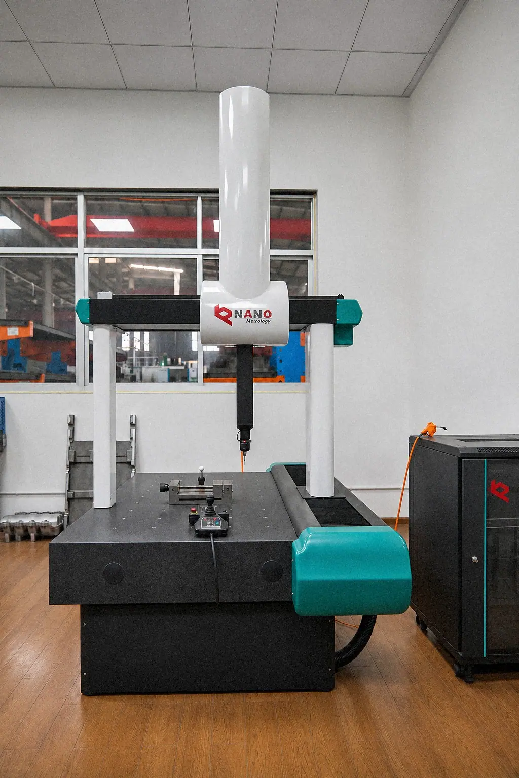
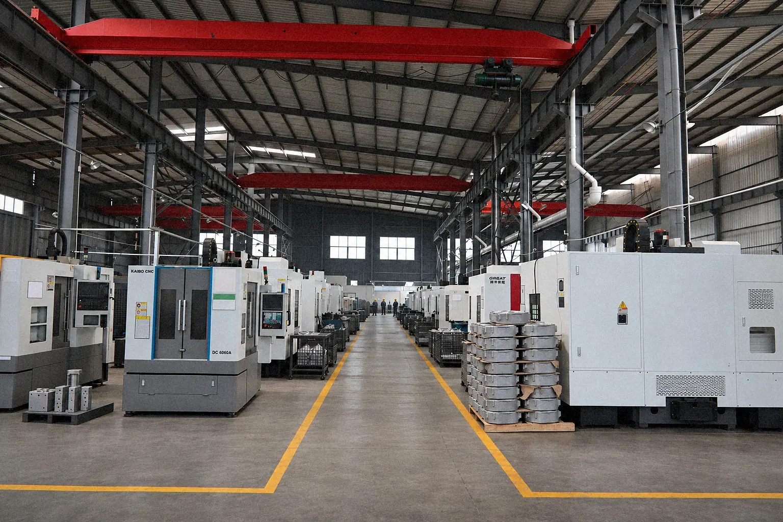
Review Bohua gravity casting capability and the quality control and inspection scope against the drawing.
At Bohua
For individually agreed critical as-cast dimensions, Bohua can reach approximately DCTG 6. For a nominal dimension above 63 mm and up to and including 100 mm, DCTG 6 corresponds to a total tolerance of 0.78 mm, or ±0.39 mm if centered on nominal.
Use this as a starting point for the drawing review, then confirm the size band and grade in the controlled ISO 8062-3:2023 table if that edition governs your order. Routine as-cast dimensions remain CT8.
Example reference: ISO 8062-3:2023, Table 7. The 0.78 mm total width is one standard value used to explain the selected-feature capability statement; it is not a Bohua measurement result.
Compare Manufacturing Routes on Equal Terms
Do not compare process accuracy through unrelated generic plus/minus ranges. Use the same nominal dimension, feature, geometry, alloy, process condition and inspection method. Ask the supplier to identify the proposed capability evidence and any design changes needed to support it.
Tool construction, core location, local section, heat treatment and machining sequence can affect the result. Separate a proposed target from demonstrated capability and from the customer's acceptance limit. A target printed in a quotation is not a completed capability study.
Prepare the Inspection Plan With the RFQ
Mark the nominal dimension and controlled feature, not only the overall part size.
- Name the standard edition and any individual exceptions.
- Define datums, part support and the inspection state.
- Distinguish casting allowances from finished dimensions.
- Identify inaccessible surfaces and how they will be verified.
- Agree sample quantity, required reports and disposition of nonconforming results.
For a suspension bracket, carry those inputs into the suspension bracket RFQ requirements.
At Bohua
Bohua can support PPAP up to Level 5 when the dimensional evidence forms part of a customer approval package.
Agree the sample quantity, inspected state and required records with the PPAP submission scope.
FAQ
Can one general casting grade control every feature?
No. Review its scope and specify individual requirements for features that need different controls.
Can I copy a CT or DCTG number from a supplier brochure?
Only as a discussion starting point. Confirm the designation, edition, dimensions and applicability in the controlled drawing package.
Should every tight feature be machined?
That is a design and manufacturing decision. Compare the required function and acceptance with a verified route instead of inferring machining need from one general tolerance grade.
Send the marked drawing and inspection expectations through the tolerance RFQ route.
Send the drawing and standard edition
Send the controlled drawing, alloy, delivery condition, annual volume and required acceptance records. Submit the RFQ details, then email your drawing for a structured quote review. Send the drawing, target alloy, finishing scope, MOQ, and delivery timing. Bohua will review it like a real sourcing project, not a generic contact request. Our engineering team can recommend the right alloy, process, and design optimizations for your specific requirements.
Send your drawing →