Ningbo Bohua Mechanical Parts Co., Ltd. · Linda, Export Sales · linda@ningbobohua.com · www.bohua-casting.com
Engineering guide
CMM Inspection for Aluminum Castings: GD&T & PPAP Guide
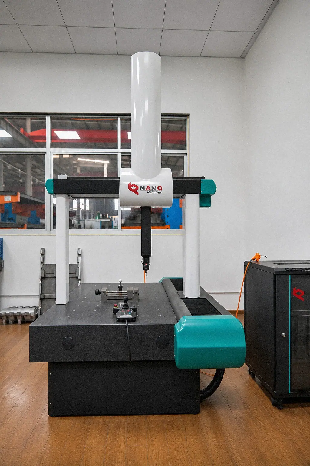
Define CMM inspection for a casting with the drawing revision, functional datums, inspection stage, and required report fields. Bohua has Hexagon Global S and NANO Metrology CMMs. Equipment identity is the starting point; the measurement method and evidence must fit the specific feature tolerances and customer requirements.
On this page
- Define the drawing, datums, and inspection state first
- Separate casting checks from final dimensional acceptance
- Choose optical scanning or tactile CMM by the question
- Agree how the drawing becomes a measurement program
- Check measurement evidence against the feature tolerance
- Make every result traceable to a drawing characteristic
- Resolve measurement disagreements before changing the part
Define the drawing, datums, and inspection state first
A useful CMM inspection request identifies the controlled drawing revision, datum reference frame, characteristics to measure, and part condition. Separate as-cast checks from final machined-part checks before agreeing the report.
At Bohua
- CMM equipment includes Hexagon Global S and NANO Metrology machines.
- The stated as-cast tolerance capability is CT8. Key dimensions after machining can reach ±0.02 mm. These are separate manufacturing capabilities, not CMM accuracy specifications or blanket limits for every feature.
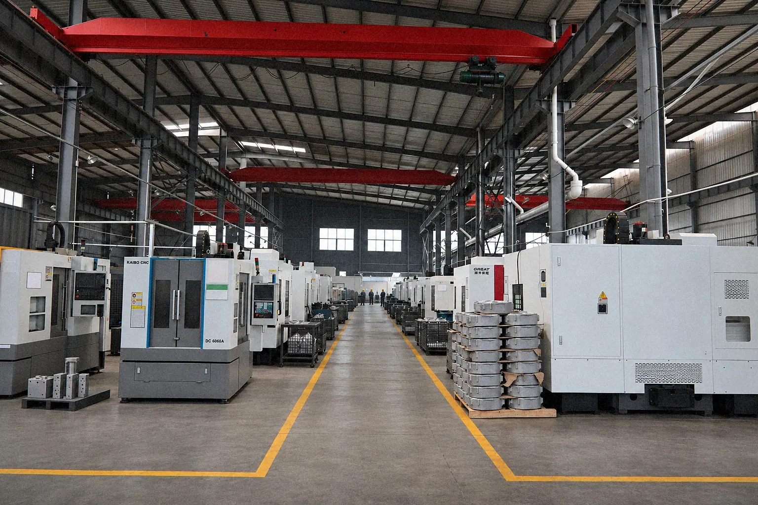
- Machining equipment includes 16 vertical machining centers, 2 CNC engraving and milling machines, 22 CNC lathes, and 2 large lathes.
- Casting, core making, tooling, T5/T6 heat treatment, CNC machining, and inspection share a site of about 16,300 m².
Confirm feature-specific acceptance during drawing review. The cast aluminum CNC machining scope explains the manufacturing route; this page defines the dimensional evidence to request.
Separate casting checks from final dimensional acceptance
Each result should identify the process stage so the buyer can tell which condition was measured.
| Inspection state | Questions to resolve | Required report context |
|---|---|---|
| As-cast | Which cast features, datum targets, and machining-stock checks are required? | Cast surfaces used for alignment, part restraint, characteristic references, and agreed acceptance limits. |
| After specified heat treatment | Does the drawing require a dimensional check at this stage before machining? | Treatment condition and features used to assess distortion or remaining stock. |
| After final machining | Which bores, mounting faces, hole patterns, and geometric tolerances control assembly? | Final datum scheme, drawing revision, measured results, limits, and disposition. |
| After finishing, if required | Does the delivered surface condition affect a controlled dimension? | Finishing state and the dimensions requiring a final check. |
Do not apply the machined ±0.02 mm capability to the entire casting. For general casting tolerance selection, use the casting tolerance specification guide.
Choose optical scanning or tactile CMM by the question
Use optical surface scanning when the question is as-cast shape or machining stock across an accessible surface, and tactile CMM when the drawing requires a datum-based size or geometric tolerance on a selected feature.
Read the scan alignment, part state, and color scale before accepting a map. An alignment chosen only to minimize the overall shape deviation does not replace the drawing datums, and neither result proves pressure-tightness.
| Question | Method | Record before accepting the result |
|---|---|---|
| As-cast shape or machining stock across an accessible surface | Optical surface scan | CAD revision, part state, alignment method, displayed deviation scale, and any region that was not scanned. |
| Datum-based size or geometric tolerance on a selected feature | Tactile CMM | Drawing datums, restraint, feature identifier, and the measured result against the stated tolerance. |
| Pressure tightness | Separate agreed leak test | A scan map or a dimensional report does not answer this question. Use the immersion leak-test specification. |
At Bohua
Bohua has a handheld 3D scanner plus Hexagon Global S and NANO Metrology CMMs. Name the method and the feature when you request a report. The equipment list is on the quality control and inspection page.
A green region on a chosen color scale is not the acceptance limit. Keep a development scan separate from a report used for shipment release.
At Bohua
Bohua uses a Mitutoyo SJ-410 roughness tester as a separate resource for surface-texture requirements.
Assign roughness its own feature location, method and result in addition to the dimensional report.
Agree how the drawing becomes a measurement program
The CMM alignment must follow the drawing's datum requirements, including the specified restraint condition.
- Datum construction: identify the primary, secondary, and tertiary datum features or targets. Do not replace a specified machined datum with a convenient cast surface.
- Fixturing: record support locations, clamping points, and whether the part is measured free or restrained as specified.
- Surface condition: distinguish cast skin from machined faces. Agree how burrs, flash, and local surface irregularities are handled without deleting real deviations.
- Probing: define accessible features, point distribution or scan paths, stylus setup, and evaluation method.
- Temperature: agree the measurement conditions and stabilization method for the part and equipment. Record conditions needed to interpret the result.
- Revision control: link the measurement program and any approved method changes to the released drawing.
For a suspension bracket, identify the mounting features and assembly datums in the automotive suspension bracket RFQ requirements. The actual drawing determines the inspection plan.
Check measurement evidence against the feature tolerance
Ask for measurement uncertainty evidence for your casting feature, probing method and inspection setup.
ISO 10360-2:2009 addresses acceptance and reverification of CMMs used for linear dimensions. Its stated scope covers Cartesian machines using contacting probes in discrete-point mode. Define your part-specific measurement method separately, and request evidence for any probing mode outside that stated scope.
Source: ISO 10360-2:2009, scope and abstract.
Request equipment performance evidence, its applicable conditions, and the method-specific uncertainty or measurement-system study required by your program. Review the fixture, part surface, alignment, probing method, and environment together. Agree any acceptance ratio against the customer's measurement requirements before applying it to your results.
Specify the drawing's governing dimensioning standard and edition. Agree the decision rule for results close to a tolerance limit before reviewing samples. A calibration record and a dimensional report answer different questions.
Make every result traceable to a drawing characteristic
Agree the report fields before measuring samples so results can be compared without reconstructing the inspection setup.
| Field group | Buyer requirement |
|---|---|
| Identity and condition | Sample identity, lot linkage, drawing revision, inspection stage, and date. |
| Characteristic | Drawing balloon reference, feature definition, datum reference frame, and applicable modifiers. |
| Result | Nominal value, tolerance limits, measured value, deviation, and disposition. Show the unit for each value. |
| Method | Equipment identity, program revision, fixture or restraint, and relevant probing settings. |
| Exceptions | Unmeasured features, alternative methods, approved deviations, and the approving role. |
Features that the CMM cannot access need a separately agreed method. Threads, surface finish, internal soundness, and pressure tightness may require evidence outside a dimensional report. For submission responsibilities, see PPAP evidence planning for aluminum castings.
At Bohua
Dimensional records can be discussed within Bohua’s PPAP support, which extends up to Level 5.
Agree the required submission level, measurement state and sample selection with the drawing-linked report scope.
Resolve measurement disagreements before changing the part
When buyer and supplier results differ, compare the methods on the same identified sample before drawing a manufacturing conclusion.
- Match the revision and state. Confirm that both reports use the same drawing and the same machining or finishing condition.
- Match the alignment. Compare datum construction, supports, restraint, and the applicable geometric tolerance interpretation.
- Match the measurement conditions. Review stabilization, probing locations, feature evaluation, and equipment evidence.
- Record the resolution. Agree the method, repeat the affected measurements, and retain the disposition with the report revision.
Send the controlled PDF drawing, 3D model where available, critical characteristics, required inspection stages, sample quantity, and preferred report fields through the casting quotation request. Include any customer measurement-system requirements with the package.
Send your drawing and dimensional inspection requirements
Submit the RFQ details, then email your drawing for a structured quote review. Not sure which process fits? Tell us what the part must do. In a free drawing review, our engineers recommend a process and suggest design changes where needed.
Send your drawing →