Ningbo Bohua Mechanical Parts Co., Ltd. · Linda, Export Sales · linda@ningbobohua.com · www.bohua-casting.com
Application
Aluminum Valve Body Manufacturer
Bohua reviews custom aluminum valve body drawings for casting, heat treatment, CNC machining, dimensional inspection, and pressure-tightness testing. Send the flow passages, ports, bores, threads, sealing interfaces, final delivery condition, and required acceptance records so we can review the manufacturing scope for your valve body.
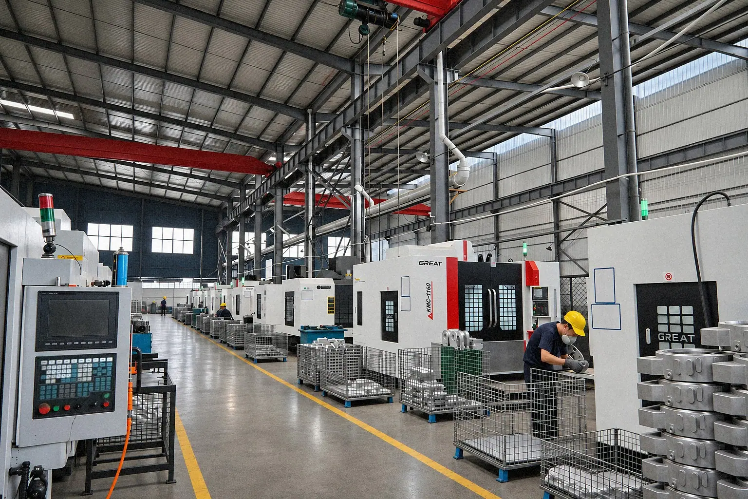
Can Bohua Manufacture Your Valve Body?
Bohua can review an aluminum valve body as a casting-only, heat-treated, or cast-and-machined component. The review must use the controlled drawing to identify internal passages, pressure boundaries, ports, functional bores, threads, sealing faces, mounting datums, cleaning needs, and the final acceptance state. Send those requirements with your drawing so we can confirm which operations fit your valve body.
- Casting experience
- Since 1994
- Tilt-pour machines
- 32
- Hot-box core shooters
- 10
- Vertical machining centers
- 16
- Immersion test range
- 3 bar or more
At Bohua
Gravity casting and tilt-pour are the principal processes. The plant has 32 tilt-pour machines, some designed and built in-house, 10 vertical gravity casting machines, and 10 hot-box core shooters. Some tilt-pour components use sand cores. A356 and ZL114 are the confirmed alloys for Bohua's gravity and tilt-pour work.
Review the aluminum gravity casting capability for equipment and range. If the manufacturing route is open, use the casting process selection guide to review the options against your passage geometry and acceptance requirements.

Map Flow Passages and Interfaces Before Quotation
A valve body quote becomes comparable only when each supplier sees the same functional boundary. Mark the passages and interfaces on the drawing so we can review the internal geometry alongside the outside shape.
| Feature group | Buyer input | Reason for the review |
|---|---|---|
| Flow passages | Passage map, wall sections, isolated cavities, and closure points | Separates casting geometry from drilled or plugged passages |
| Ports and threads | Thread standard, class, depth, chamfer, and gauge requirement | Defines machining and inspection scope |
| Functional bores | Datum relationship, tolerance, geometry, and final finish | Identifies fixture and dimensional-report requirements |
| Sealing interfaces | Gasket faces, O-ring grooves, sealing lands, and surface requirements | Defines final acceptance state and test boundary |
| Cross-holes | Intersection, deburring, plugging, and cleanliness requirements | Prevents hidden scope differences between quotes |
Use only the features present on the controlled drawing. Identify whether your design includes a spool bore, isolated cavity, plug, or separate cover. Use the assembly design to determine which checks apply to your valve body.
Resolve Special Interfaces Before Supplier Selection
Identify special interfaces before the manufacturing scope is agreed. The valve body RFQ guide organizes the drawing inputs and acceptance questions by feature.
- Cartridge cavities: specify screw-in or slip-in construction and the selected cartridge and controlled cavity reference.
- Permanent closures: define the prepared seat and assign closure supply, installation, and acceptance responsibilities.
- Mating interfaces: release the exact mounting interface, end-connection geometry, and seat-to-guide datum chain where applicable.
- Remaining wall: separate the final required minimum from service allowance, casting stock, and machining allowance.
Tooling and Casting Route
The tooling review should connect core strategy, feeding, machining stock, and inspection access to the actual passage geometry. The same outside envelope can require a different route when the internal walls or final machined exposure changes.
At Bohua
Bohua designs and makes molds in-house with UG and SolidWorks and uses AnyCasting for casting simulation. Most molds use GB 45 carbon steel, while H13 is used for higher requirements. A356 permanent molds typically last about 20,000–50,000 shots. That range applies to GB 45 carbon-steel molds; H13 molds last about 100,000 shots with regular maintenance. First article takes 5–6 weeks from drawing confirmation.
T5 and T6 heat treatment are performed in-house. Send the drawing so we can agree the casting, core, heat-treatment, and machining sequence for its passage geometry and finished interfaces.
State the required alloy, temper, governing specification, material evidence, annual volume, and release pattern. Bohua quotes by annual volume, and small batches are negotiable. The A356 material and specification page can help organize the material discussion. Confirm whether your valve body specification calls for A356 or another alloy so we can review the required material.
CNC Scope for Ports, Bores, Threads, and Faces
List machining operations feature by feature. A line that says “machine to drawing” can hide differences in fixture scope, datum transfer, bore finishing, thread inspection, cross-hole deburring, cleaning, and dimensional reporting.
At Bohua
Machining equipment includes 16 vertical machining centers, 2 CNC engraving and milling machines, 22 CNC lathes, and 2 large lathes. Bohua's confirmed general capability is CT8 in the as-cast condition and ±0.02 mm for critical machined dimensions. Identify each feature's manufacturing condition and required tolerance so we can review these separate capabilities against your drawing.
- Datums: identify the primary, secondary, and tertiary references for machining and inspection.
- Ports and threads: list the features, standards, depths, gauges, and record frequency.
- Bores: identify diameter, geometry, position, surface requirement, and the controlling datum.
- Sealing faces: state flatness and surface requirements at the final acceptance stage.
- Cleanliness: define cross-hole deburring, loose-chip acceptance, washing, preservation, and packaging.
Review Bohua's casting and CNC machining scope and the drawing requirements for casting RFQs before comparing suppliers.

Define the Pressure-Tightness Test Boundary
A component test and a complete-valve test answer different questions. The RFQ should identify which cavities are isolated, which ports are closed, the state of the sealing surfaces, and which responsibilities remain with the final assembler.
- Mark the tested cavity or pressure path and every temporary or permanent closure.
- State the test pressure with units, duration, acceptance rule, sampling, and required record.
- Identify whether testing occurs before machining, after machining, after finishing, or in the final supplied condition.
- Separate body pressure-tightness from flow, actuation, trim, assembly, service, and complete-valve certification.
Bohua test boundary
Bohua's pressure-tightness test method is air-under-water immersion at 3 bar or more. The buyer defines pressure, duration, acceptance criterion, test stage, sampling, closures, and records. Impregnation is performed by a qualified subcontractor only with customer approval.
The leak-tight aluminum casting page explains how casting, machining, test, and impregnation scope should be separated.
Inspection Evidence for Valve Body Acceptance
Specify the record before requesting the quote. Define the characteristics, datums, methods, frequency, acceptance references, and report formats so we can match the inspection equipment and records to your project.
| Checkpoint | Bohua capability | Project input |
|---|---|---|
| Material identity | Oxford optical emission spectrometer | Alloy, temper, specification, and certificate format |
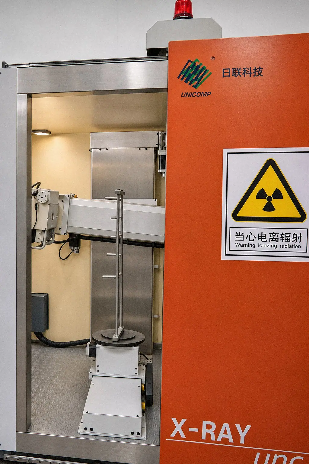
| Internal inspection | Unicomp UNC-160 and Y.MU2000-D X-ray systems | Zones, views, frequency, acceptance reference, and record format |
| Dimensions | Hexagon Global S and NANO Metrology CMM systems | Datums, critical characteristics, sampling, and report layout |
| Submission package | PPAP support up to Level 5 | Submission level, deliverables, timing, and approval authority |
Bohua's quality management system is certified to IATF 16949:2016 by NQA, with the certificate valid through November 20, 2027. Use the quality-control and inspection page to review the wider equipment list.
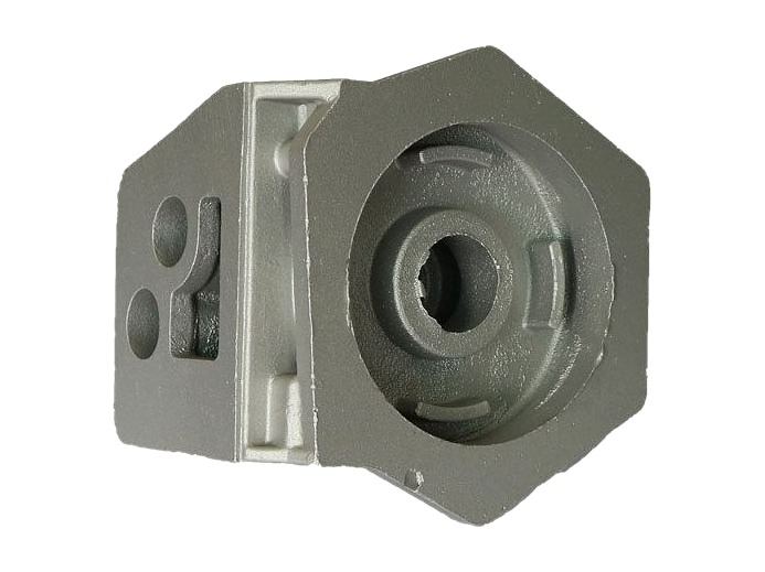
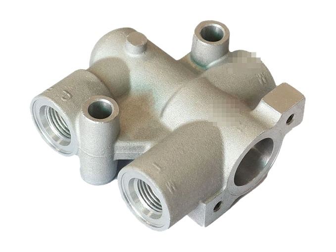
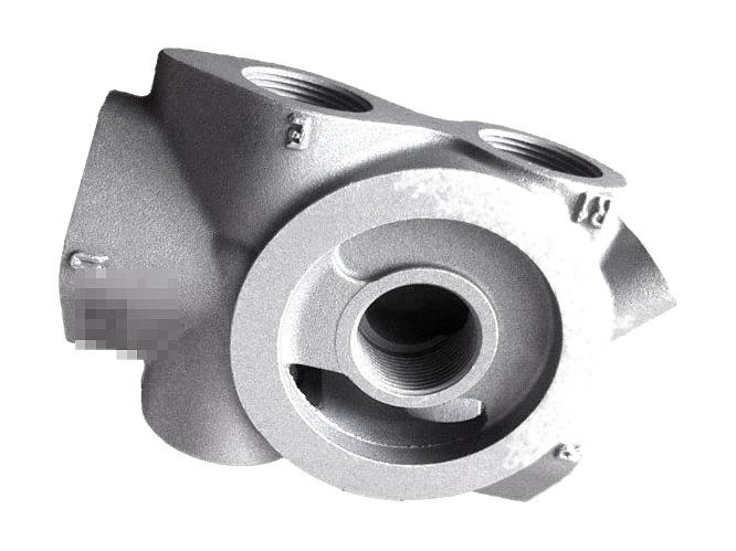
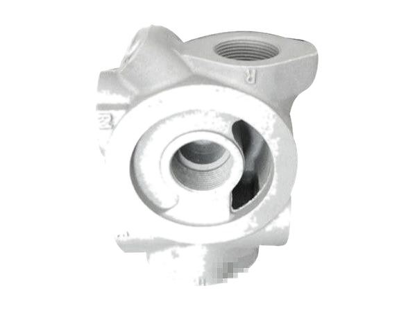
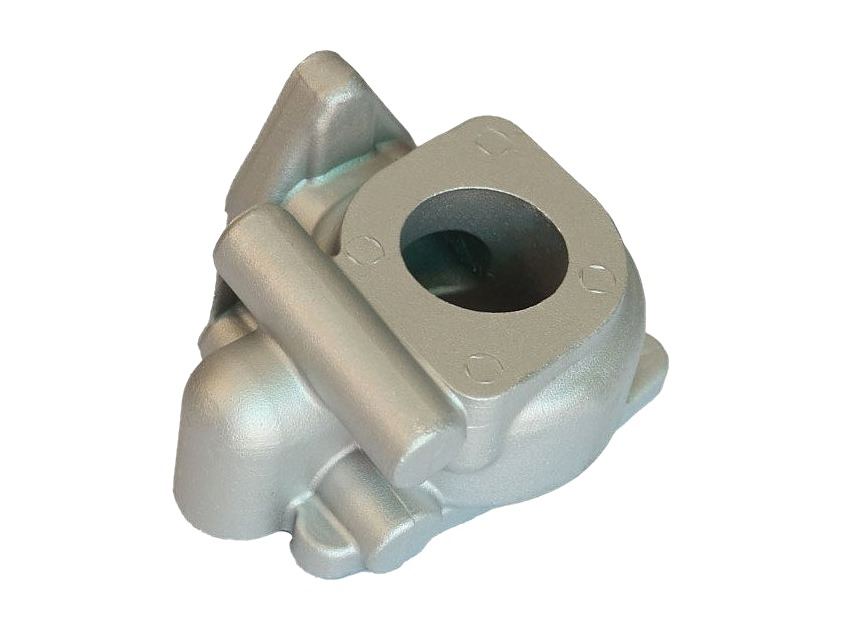
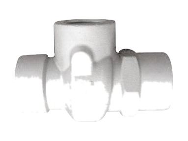
Valve and Flow-Body Casting Examples
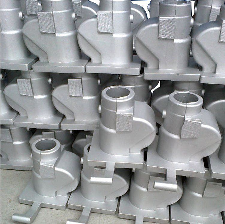
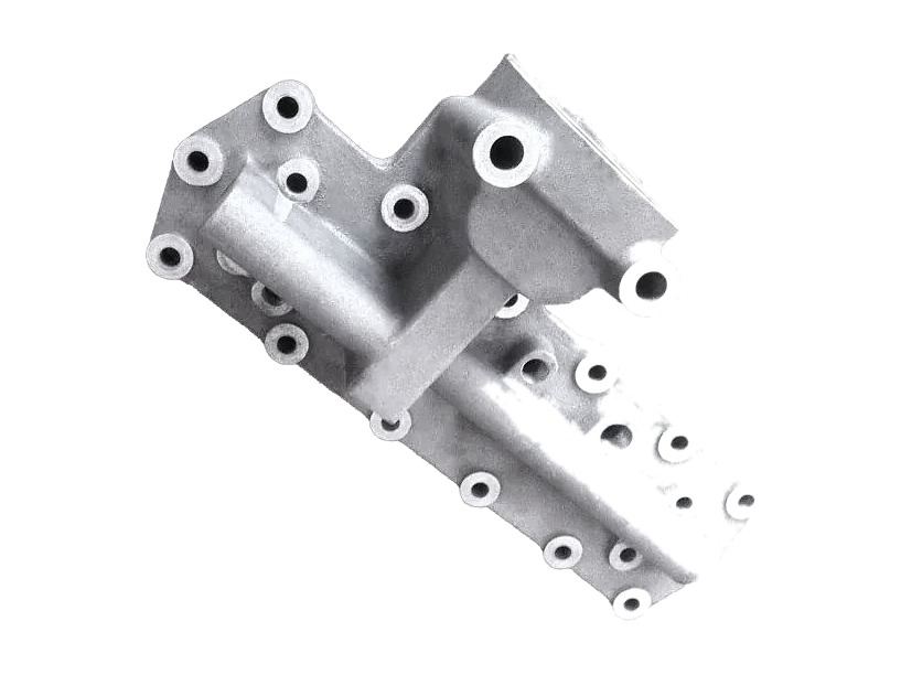
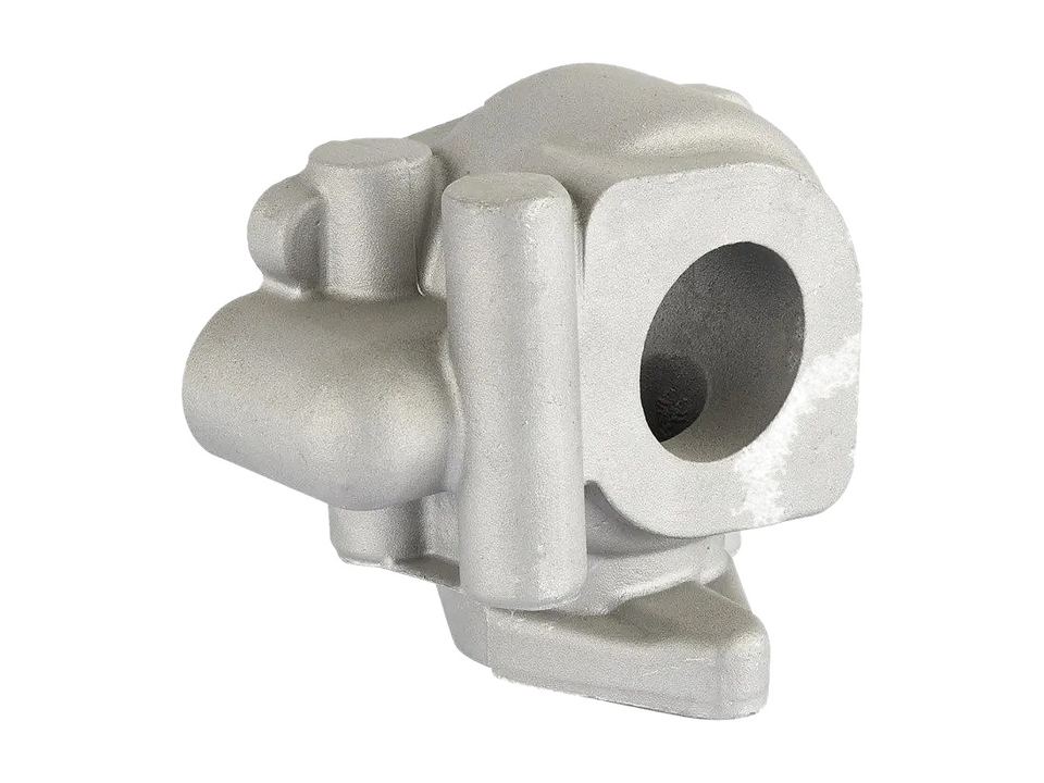
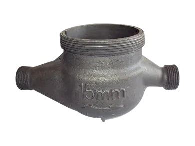
These photographs show aluminum parts Bohua has made. Use the visible geometry and part families to discuss your design. Include the required alloy, process, dimensions, pressure rating, tolerance, cleanliness, and inspection criteria with your drawing. Customer logos and part numbers are masked.
Have a similar part? Send your drawing
What to Send for a Valve Body Review
A complete package makes the casting, machining, cleaning, testing, and inspection assumptions visible before suppliers are compared.
- Controlled geometry. Send the current 2D drawing and a STEP model when available.
- Functional map. Mark passages, pressure boundaries, isolated cavities, ports, bores, cross-holes, plugs, and sealing interfaces.
- Material and delivery state. Define alloy, temper, governing specification, surface treatment, cleaning, preservation, and final supplied condition.
- Machining plan. Identify datums, critical dimensions, threads, gauges, surface requirements, deburring, and fixture responsibilities.
- Acceptance plan. List dimensional, material, internal-inspection, pressure-tightness, PPAP, traceability, sampling, and record requirements.
- Commercial inputs. Give sample needs, annual volume, release pattern, tooling status, destination, and packaging requirements.
When the package is ready, submit the valve body RFQ. Use the aluminum casting RFQ checklist if the project inputs are still being assembled.
Valve Body Manufacturing Questions
Does Bohua supply raw or machined valve bodies?
The reviewed scope may include casting, in-house T5 or T6 heat treatment, and CNC machining. The drawing and quotation must state the final delivery condition and identify finishing, cleaning, inspection, packaging, and buyer-owned operations.
What should the valve body specification include?
Provide controlled documents defining alloy, temper, process, pressure rating, dimensions, tolerances, internal passage condition, and cleanliness. Specify the required test results and acceptance criteria so we can review the complete valve body requirement with you.
Can Bohua perform pressure-tightness testing?
Yes, within the confirmed air-under-water immersion capability of 3 bar or more. The project specification still defines the tested boundary, pressure, duration, acceptance rule, test stage, sampling, closures, and records.
Does a body quotation include a complete valve?
The body quotation covers the agreed component scope. Define trim, actuation, assembly, flow performance, service validation, and complete-valve certification separately. Assign any component-supplier obligation explicitly in the controlled project scope so we can review it.
Send your valve body drawing for a port and sealing review
Share the flow passages, port threads, sealing faces, test requirement and annual volume. Not sure which process fits? Tell us what the part must do. In a free drawing review, our engineers recommend a process and suggest design changes where needed.
Send your drawing →